Thumb push button starter wiring diagram push button starter switch wiring diagram luxury help wiring up push start button ign switch 88 144174.jpeg
25/04/2024 17:51 - Cbbysfpfri -

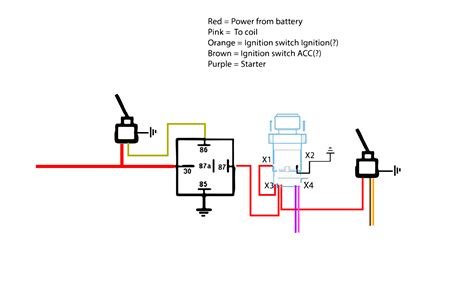
Nov 1, 2022 · Understanding the Starter Solenoid Wiring Diagram Starter Solenoid Wiring Diagram. ples of electromagnetism in its work. When the ignition key is turned on, it sends an electrical signal to the solenoid, which then engages the starter motor and cranks the engine. It act as safety solenoid switch, preventing the starter motor from engaging ... Keyless Ignition System, Push To Start, 25mm OE Style Button, Kit. Part Number: IDT-2600681100. Not Yet Reviewed. Estimated Ship Date: Oct 9, 2023 (if ordered today) Drop Ship. Free Shipping. $20.00 Summit Bucks. Special Order.Sep 22, 2020 · Brett Martin. September 22, 2020. Cub Cadet Ignition Switch Wiring Diagram – Database. Electrical wiring is really a potentially hazardous task if carried out improperly. One need to never attempt functioning on electrical cabling without knowing the below tips and tricks followed by even the many experienced electrician. Thanks Tim, it is really hard to read. My 52 AD came with a starter button on the dash with a key switch. Key cluster has three prongs one red hot wire is connected to the key and there are couple of blue wires goes to the starter button. whoever originally convereted to 12V used all blue wires so it was really difficult to findout which blue wire go where. Aug 30, 2020 - Push button Ignition Switch Wiring Diagram . Push button Ignition Switch Wiring Diagram New. Push button Switch Wiring Diagram New Push button Switch Wiring. Simple Push button Wiring Enthusiast Wiring Diagrams •. Push button Switch Wiring Diagram 2018 Ignition Relay Wiring DiagramAug 30, 2020 - Push button Ignition Switch Wiring Diagram . Push button Ignition Switch Wiring Diagram New. Push button Switch Wiring Diagram New Push button Switch Wiring. Simple Push button Wiring Enthusiast Wiring Diagrams •. Push button Switch Wiring Diagram 2018 Ignition Relay Wiring Diagram Mar 19, 2023 · I also review some simple things, like choosing the right fuse size, choosing wire size, how to wire a relay, how to wire a fuel pump, and how to wire an ignition switch to a push button start. There are four basic wiring combinations: a) Full-voltage non-reversing 3-phase motors. b) Full-voltage reversing 3-phase motors. c) Single-phase motors. d) Wye-delta open transition 3-phase motors. You must supply a disconnect switch, proper sized wire, enclosures, terminal blocks and any other devices needed to complete your circuit.2. Single Starter Relay Car Starter Wiring Diagram When large power starter is equipped, in order to reduce intensity of the current that passes through the ignition switch and avoid ablation of the switch, the start relay is often used to control the heavy current of the starter solenoid switch, and the ignition switch( Start position) is used to control the low current of the relay coil. introduction This booklet has been prepared as a guide to some of the useful ways Allen-Bradley’s manual and magnetic across-the-line starters may be applied. It will also serve as a useful aid where simple wiring systems are to be studied. When applying these diagrams, it is well to remember that the features described inFeb 16, 2013 · RVBOATPAT Push Button Starter Switch 12V 50A Engine Start Button 12 Volt 50 Amp Push to Start Ignition Kit Blue Led for Marine Vehicle Racing Car Truck RV (51) $11.99 ($0.75/Ounce) Jul 31, 2011 · Its been awhile since I worked on that old of wiring. I think that your switch is a 3 position switch. If that is the case You should have 1terminal (probably the center) should have power coming in Either from hot side of button or directly from the starter.The other terminals Idont think it matters which except for key orientation should both be power out.1 is for accessory only and of ... Step 4. Using the crimping tool, remove the insulation from about 1/4-inch of the wire and attach an eyelet connector that is of appropriate size to fit over the positive side stud of your solenoid. Crimp the connector onto the wire firmly and then slide the eyelet over the positive side stud of the solenoid and reattach the nut.Which is exactly what a remote starter switch is doing. All that they are is a switch—either pistol-grip or push-button—with two wires with alligator clips on the ends pre-connected to it. You attach one clip to battery positive, the other to the small terminal on the solenoid from the ignition switch, and push the button.All it would take is a toggle switch of your choice per ign/acc wire, a relay per ign/acc wire. You would also need the push button and a relay for the starter. Then wire the toggles to pass a ground and all the relays like this diagram. Certified Security Specialist Always check info with a digital multimeter.Hi, I've got a 1950's motor that i would like to wire to a push button on/off switch. Is the a push button switch on the market to do what i want in the diagram or a way of wiring one as i can not find any on ebay? The only ones i can find that is a close match is the 3 phase switches like this one (ebay No. 290930766073).There is no difference in wiring the system. It is simply that all three switches are built into the key-style ignition switch. Positive goes to one terminal on two of the three switches. The other terminal goes to whatever that switch controls. 1) starter solenoid, 2) choke/primer, and 3) magneto.6 Prong Ignition Switch Wiring Diagram: Step 4. Look for the position of the positive solenoid; most of the time, the lower terminal has the plus sign. Get a wire with clips on both sides and connect the “S” terminal to the positive terminal of the solenoid. 6 Prong Ignition Switch Wiring Diagram: Step 5. Connect the magneto to the switch.Feb 11, 1999 · There are four basic wiring combinations: a) Full-voltage non-reversing 3-phase motors. b) Full-voltage reversing 3-phase motors. c) Single-phase motors. d) Wye-delta open transition 3-phase motors. You must supply a disconnect switch, proper sized wire, enclosures, terminal blocks and any other devices needed to complete your circuit. Sep 29, 2018 · Remove the screw from the back of your push button switch, then join the connector and switch. Strip the remaining wire’s insulation about 1/4 inch down so you can install a crimp connector, remove the screw from the other side of your push button switch and join the connector and the switch. Route the wire to your battery’s positive, once ... deathphoenix99 · #12 · Apr 17, 2012. You need a toggle switch and a push button for this to work. The toggle switch either has to be rated high enough for all of the electronics to go through it or use a relay that is rated high enough. The push button starter has to be rated enough as well, or use a relay.Splice into the side of the cut that goes to the relay. (You could also tap into it rather than cutting it.) That wire would go to one side of your push button switch. Wire the other side of the switch to a battery source. The safest way is to wire it to a source (like a fuse tap) that is hot only when the key is on.Oct 26, 2014 · This is how to run wiring for a toggle on/off switch and a push button start. This is the most basic wiring you need to run your mower. Step 4. Using the crimping tool, remove the insulation from about 1/4-inch of the wire and attach an eyelet connector that is of appropriate size to fit over the positive side stud of your solenoid. Crimp the connector onto the wire firmly and then slide the eyelet over the positive side stud of the solenoid and reattach the nut.The push button starter switch has a battery cable plus a smaller wire connected to one terminal and big cable on the other connects to starter motor, just like in the diagram that you first posted. Re: Pushbutton Starter Wiring for 9N in reply to [email protected], 11-20-2016 12:57:14. f Typical Wiring Diagrams. 4 for Push Button Control Stations. Pilot Light Selection Pilot Light selection is based on the following factors; Voltage, Lamp Requirements, Environment, and Cost. 4. The voltage of a pilot light must match the voltage supply. If both AC and DC voltage sources are available, AC voltage.Nov 21, 2016 · CVPost-HCooke wrote: (quoted from post at 20:58:08 11/20/16) 9Ns do not have solenoids. The early 9Ns have a dash mounted starter button, like in Del's picture. The cable from the starter switch goes directly to the lug on top of the starter. Google "wiring diagrams by JMOR" and find the early 9N diagram. Aug 24, 2023 · 6 Prong Ignition Switch Wiring Diagram: Step 4. Look for the position of the positive solenoid; most of the time, the lower terminal has the plus sign. Get a wire with clips on both sides and connect the “S” terminal to the positive terminal of the solenoid. 6 Prong Ignition Switch Wiring Diagram: Step 5. Connect the magneto to the switch. 2. Single Starter Relay Car Starter Wiring Diagram When large power starter is equipped, in order to reduce intensity of the current that passes through the ignition switch and avoid ablation of the switch, the start relay is often used to control the heavy current of the starter solenoid switch, and the ignition switch( Start position) is used to control the low current of the relay coil. Electrical & Electronic Symbols www.electrical-symbols.com Symbols of Switches of Two and Three Positions [ Go to Website ] 5/10 All Electrical & Electronic Symbols in https://www.electrical-symbols.comPush Button Momentary Starter Switch, Ampper Heavy Duty Momentary Switch for 12V Engine Start, Horn, Electrical Equipment Ignition and More (Black, Pack of 3) 196. 100+ bought in past month. $1199 ($4.00/Count) FREE delivery Sun, Sep 10 on $25 of items shipped by Amazon. Or fastest delivery Sat, Sep 9. Step 1: Obtain a circuit diagram. Step 2: Locate all components that need wiring. Step 3: Connect the switch to ground. Step 4: Connect the switch to the Solenoid. Step 5: Wire the magneto to the switch. Step 6: Provide voltage by connecting the battery. Step 7: Connect the accessories/ lights.This is a single pole double throw push button. There is no open position is this switch. It makes contact (ON state) in both positions. Pushing & holding the button will switches the circuit unto the other terminal. Releasing the button will return the contact to its original position.Jan 18, 2018 · There is no difference in wiring the system. It is simply that all three switches are built into the key-style ignition switch. Positive goes to one terminal on two of the three switches. The other terminal goes to whatever that switch controls. 1) starter solenoid, 2) choke/primer, and 3) magneto. Gardner Bender. Calterm. ELEGRP. NSi Industries. Name. 10-Amp Single-Pole Maintained Contact Push-Button Switch, Black (1-Pack) 60 Amp Heavy Duty Sealed Push Button Starter Switch. 15 Amp Combination Single Pole Toggle Switch with Pilot Light, Wall Plate Included, White (2-Pack) 20 Amp Double-Pole Single-Throw Toggle Switch.APIELE Push Start Ignition Switch, Off- (ON) Instant Engine Start Push Button Switch 19mm, 12V Waterproof Car Engine Push Button Switch with LED Light for Car (Blue LED) 26. $1399. FREE delivery Wed, Jun 14 on $25 of items shipped by Amazon. Or fastest delivery Tue, Jun 13. JEGS High PerformanceKeyless Ignition System, Push To Start, 25mm OE Style Button, Kit. Part Number: IDT-2600681100. Not Yet Reviewed. Estimated Ship Date: Oct 9, 2023 (if ordered today) Drop Ship. Free Shipping. $20.00 Summit Bucks. Special Order.Here a 2-way push-button switch is wired to a lamp with 2 bulbs. This diagram can be used to rewire an old push-button lamp with a new switch replacement. The hot wire from the cord is connected directly to the black wire on the switch and the neutral is spliced to the neutral contact on each bulb sockets. The red and blue wires from the switch ...Start Stop Push Button Switch Wiring Diagram from www.industrial-electronics.com. Effectively read a electrical wiring diagram, one has to know how typically the components within the method operate. For example , when a module is powered up and it also sends out a signal of half the voltage and the technician would not know this, he'd think he ...Feb 5, 2020 · Name: allen bradley motor starter wiring diagram – 40 super allen bradley motor starter wiring diagram nawandihalabja rh nawandihalabja allen bradley proximity switch File Type: JPG Source: tinyforge.co Starter Switch for Delco Starters …LP) ], JetStar 2, 335, 445 Oliver - Fits: Super 55 (with 6 volt starter 1107147) White - Replaces: 1E7392 * Also fits SILVER KING Model 42 etc. with DELCO saddle mount switch* Does not fit Autolite* Fits following Delco Starter numbers: 1107017, 1107021, 1107029, 1107036, 1107043, 1107058, 1107060,… Hi, I've got a 1950's motor that i would like to wire to a push button on/off switch. Is the a push button switch on the market to do what i want in the diagram or a way of wiring one as i can not find any on ebay? The only ones i can find that is a close match is the 3 phase switches like this one (ebay No. 290930766073).Shop for the best Push To Start Switch for your vehicle, and you can place your order online and pick up for free at your local O'Reilly Auto Parts.Splice into the side of the cut that goes to the relay. (You could also tap into it rather than cutting it.) That wire would go to one side of your push button switch. Wire the other side of the switch to a battery source. The safest way is to wire it to a source (like a fuse tap) that is hot only when the key is on.RVBOATPAT Push Button Starter Switch 12V 50A Engine Start Button 12 Volt 50 Amp Push to Start Ignition Kit Blue Led for Marine Vehicle Racing Car Truck RV (51) $11.99 ($0.75/Ounce)Understanding the Starter Solenoid Wiring Diagram Starter Solenoid Wiring Diagram. ples of electromagnetism in its work. When the ignition key is turned on, it sends an electrical signal to the solenoid, which then engages the starter motor and cranks the engine. It act as safety solenoid switch, preventing the starter motor from engaging ...Mar 19, 2023 · I also review some simple things, like choosing the right fuse size, choosing wire size, how to wire a relay, how to wire a fuel pump, and how to wire an ignition switch to a push button start. of information and help . ... www.ntractorclub.com. Ford Wiring Diagram . POINTS COIL 12V DASH PANEL AMMETER TERMINAL BLOCK 4— KEY SWITCH STARTER BUTTON CHAS'S GRD ... The EZ manual shows a 4 post ignition switch, but the factory F1 ignition switch is only 3 post and I have the push button starter button. The EZ instructions state to connect the wires in the following manner: IGN SW Power wire --> Bat terminal. IGN SW Start --> ST terminal. IGN SW Acc --> Acc terminal. IGN SW Coil & IGN SW IGN --> IGN terminal.Aug 5, 2021 · Use the instructions in the kit to locate and connect the corresponding wires from the kit to the ignition wires on the car. Locate the brake switch wire and connect the ring transponder to it to complete the connection. Connect both systems with the transponder. Be sure to check that the ignition system works as intended. The momentary start switch should have 4 terminals. Two will be shorted together and hooked to the yellow wires, and one of the other terminals will be hooked to a red/blue (start) and the other terminal will hook to a brown/pink (resistor bypass). The toggle switch will have 4 terminals also.The relay is energized via the toggle. That applies power to the output of the relay (Terminal 87). This would essentially be your accessory power as well as power to the coil via ignition relay. This power is stopped from going to the starter solenoid and starting wire to the coil/resistor by the push button.Push button Ignition Switch Wiring Diagram . Push button Ignition Switch Wiring Diagram New. Push button Switch Wiring Diagram New Push button Switch Wiring. Simple Push button Wiring Enthusiast Wiring Diagrams •. Push button Switch Wiring Diagram 2018 Ignition Relay Wiring DiagramSep 22, 2020 · Brett Martin. September 22, 2020. Cub Cadet Ignition Switch Wiring Diagram – Database. Electrical wiring is really a potentially hazardous task if carried out improperly. One need to never attempt functioning on electrical cabling without knowing the below tips and tricks followed by even the many experienced electrician. Mar 6, 2022 · 35 Lovely Push Button Starter Wiring Diagram Diagram Wire Electrical Wiring Diagram ... Help Hot Rod Forum Hotrodders Inside Diagram On Chevy C10 Ignition Switch ... Push-button. Push-button switches are the classic momentary switch. Typically these switches have a really nice, tactile, “clicky” feedback when you press them. They come in all sorts of flavors: big, small, colorful, illuminated (when an LED shines up through the button). They might be terminated as through-hole, surface-mount, or even ...The starter switch is just a normally-open single-pole push-button. The starter solenoid usually has two small terminals and two large terminals. Wire one small terminal to the battery side of the solenoid and the other small terminal to the starter switch. The other side of the starter switch goes to a good grounding point.Electric parts needed for the wiring above: B1 = MCB 5A 3 phase. M1 = Motor 1.5kW 380V 3Phase. #1 = Magnetic contactor 220VAC. TOR = Thermal Overload Relay 2.8A. S1 = Push Button Switch ( PTB non latching - Stop switch) S2 = Push Button Switch (PTM non latching - Start switch) L3 = Pilot lamp 220VAC.The procedure for wiring an ignition switch is as follows: Step 1: Disconnect the negative battery terminal To begin with, the negative battery terminal must be disconnected before locating the positive power lead to the switch. This is followed by installing the right terminal end on the power lead wire and connecting it to the battery terminal.There is no difference in wiring the system. It is simply that all three switches are built into the key-style ignition switch. Positive goes to one terminal on two of the three switches. The other terminal goes to whatever that switch controls. 1) starter solenoid, 2) choke/primer, and 3) magneto.2,564. Location: Plano US. If the foggy old brain remembers right we used to use starters from 49-53 cars as they were the push button type. A wire from the accessory terminal on the switch to one side of the push button and then another wire from the other side of the switch to the solenoid terminal.of information and help . ... www.ntractorclub.com. Ford Wiring Diagram . POINTS COIL 12V DASH PANEL AMMETER TERMINAL BLOCK 4— KEY SWITCH STARTER BUTTON CHAS'S GRD ...2. Single Starter Relay Car Starter Wiring Diagram When large power starter is equipped, in order to reduce intensity of the current that passes through the ignition switch and avoid ablation of the switch, the start relay is often used to control the heavy current of the starter solenoid switch, and the ignition switch( Start position) is used to control the low current of the relay coil.Sep 29, 2011 · Location: Michigan. Posts: 24. Re: Wiring up a Push Start Button. Run the main power wire from the battery to a toggle swith. Run the other wire out of the toggle switch to the push button. Run the next wire out of the push button down to the starter itself. Its the larger screw not the small one. May 10, 2015 · I hooked the drop key switch to a relay , the switch broke the ground . The relay was the power to my cal custom ignition switch witch was also a start switch . It is like a light switch , pull out ig. Is on pull out , spring loaded , and it starts . You don't have to use this switch . Just have relay go to ig. And start button . Push-button. Push-button switches are the classic momentary switch. Typically these switches have a really nice, tactile, “clicky” feedback when you press them. They come in all sorts of flavors: big, small, colorful, illuminated (when an LED shines up through the button). They might be terminated as through-hole, surface-mount, or even ...This includes issues such as loose connections, incorrect wiring sequences, and incorrect placements for the push button. Understanding the Schematic The first step in using a visual guide to wiring a push button start diagram is to understand the schematic. If you have some of these it will be cheaper. Make sure this connection is solid and ...Jul 30, 2018 · Wiring Diagram Pictures Detail: Name: push button station wiring diagram – MG ZR Rover 200 25 MK1 wiring to MK2 Dash Switches Conversion Guide. File Type: JPG. Source: szliachta.org. Size: 111.34 KB. Dimension: 787 x 485. Gardner Bender. Calterm. ELEGRP. NSi Industries. Name. 10-Amp Single-Pole Maintained Contact Push-Button Switch, Black (1-Pack) 60 Amp Heavy Duty Sealed Push Button Starter Switch. 15 Amp Combination Single Pole Toggle Switch with Pilot Light, Wall Plate Included, White (2-Pack) 20 Amp Double-Pole Single-Throw Toggle Switch. The relay is energized via the toggle. That applies power to the output of the relay (Terminal 87). This would essentially be your accessory power as well as power to the coil via ignition relay. This power is stopped from going to the starter solenoid and starting wire to the coil/resistor by the push button.Keyless Ignition System, Push To Start, 25mm OE Style Button, Kit. Part Number: IDT-2600681100. Not Yet Reviewed. Estimated Ship Date: Oct 9, 2023 (if ordered today) Drop Ship. Free Shipping. $20.00 Summit Bucks. Special Order. Cambridge 15 Amps Brass Push Button Starter Ignition Switch. Part # SW12923. SKU # 768400. $1299.Keyless Ignition System, Push To Start, 25mm OE Style Button, Kit. Part Number: IDT-2600681100. Not Yet Reviewed. Estimated Ship Date: Oct 9, 2023 (if ordered today) Drop Ship. Free Shipping. $20.00 Summit Bucks. Special Order. Electrical & Electronic Symbols www.electrical-symbols.com Symbols of Switches of Two and Three Positions [ Go to Website ] 5/10 All Electrical & Electronic Symbols in https://www.electrical-symbols.comFind the wire to be connected to the equipment, distinguish the live line and zero lines. The red line is the life line and the blue one is the zero line. You can also test with an electric pen ...of information and help . ... www.ntractorclub.com. Ford Wiring Diagram . POINTS COIL 12V DASH PANEL AMMETER TERMINAL BLOCK 4— KEY SWITCH STARTER BUTTON CHAS'S GRD ...the safety switches have 4 wires each, 2 are connected with the button out and the other two are not connected with the button pushed in. push the button in and this reverses so the "open" connection closes and the "closed" connection opens. the way these are wired is, the wire going to the starter is broken through these switches if the blade is engaged or if the brake pedal is not pushed in ...2,564. Location: Plano US. If the foggy old brain remembers right we used to use starters from 49-53 cars as they were the push button type. A wire from the accessory terminal on the switch to one side of the push button and then another wire from the other side of the switch to the solenoid terminal.Aug 18, 2020 · What is the internal structure diagram of the push button switch? From: Quisure 2020-08-18. The push button switch is divided into start button (green button), stop button (red button) and compound push button switch (the color is not necessarily), and the different functions are determined by the position of the internal bridge-type moving ... Oct 26, 2014 · This is how to run wiring for a toggle on/off switch and a push button start. This is the most basic wiring you need to run your mower. 12volts white (120A) + dash fuse box, white 1 pin plug (3E), pin 1. Starter blue + ignition switch, white 8 pin plug, pin 7. Notes: On vehicles with Smart Key, the SS1 - SS2 wires are red-purple (-) at the engine switch, black 10 pin plug, pins 5 and 1. Second Starter lt. green + ignition switch, white 8 pin plug, pin 3.Mar 27, 2020 · The procedure for wiring an ignition switch is as follows: Step 1: Disconnect the negative battery terminal To begin with, the negative battery terminal must be disconnected before locating the positive power lead to the switch. This is followed by installing the right terminal end on the power lead wire and connecting it to the battery terminal. Electric parts needed for the wiring above: B1 = MCB 5A 3 phase. M1 = Motor 1.5kW 380V 3Phase. #1 = Magnetic contactor 220VAC. TOR = Thermal Overload Relay 2.8A. S1 = Push Button Switch ( PTB non latching - Stop switch) S2 = Push Button Switch (PTM non latching - Start switch) L3 = Pilot lamp 220VAC.f Typical Wiring Diagrams. 4 for Push Button Control Stations. Pilot Light Selection Pilot Light selection is based on the following factors; Voltage, Lamp Requirements, Environment, and Cost. 4. The voltage of a pilot light must match the voltage supply. If both AC and DC voltage sources are available, AC voltage.USING THE ENGINE STARTER SWITCH Starting the engine can be done with the push type starter after the key has been put into the ON position. (this does not apply to standard push type starters) When engine is stopped, the random flashing light of the switch button brings about a greater threat than one which blinks at a set interval and hence ... There is a "BATT A" and a "BATT B" terminal at the switch, one is (+) 12 Volts with respect to chassis ground and the other is (-) 12 Volts that those wires connect to. or our website nor are we. Many thanks for visiting at this website. Here is a excellent photo for john deere starter diagramweb.net have been looking for this image via on line ...All it would take is a toggle switch of your choice per ign/acc wire, a relay per ign/acc wire. You would also need the push button and a relay for the starter. Then wire the toggles to pass a ground and all the relays like this diagram. Certified Security Specialist Always check info with a digital multimeter.Aug 30, 2020 - Push button Ignition Switch Wiring Diagram . Push button Ignition Switch Wiring Diagram New. Push button Switch Wiring Diagram New Push button Switch Wiring. Simple Push button Wiring Enthusiast Wiring Diagrams •. Push button Switch Wiring Diagram 2018 Ignition Relay Wiring DiagramL. lanierledford · #2 · Aug 1, 2008. push button starter botton. All you need is a hot wire to the starter button, then from the starter button to the s terminal ( inside next to the engine) on the starter and a 14 gage wire should feed the sol. fine. When the button is released it will open the circuit and stop the starter motor.Oct 25, 2009 · The momentary start switch should have 4 terminals. Two will be shorted together and hooked to the yellow wires, and one of the other terminals will be hooked to a red/blue (start) and the other terminal will hook to a brown/pink (resistor bypass). The toggle switch will have 4 terminals also. Step 1: Obtain a circuit diagram. Step 2: Locate all components that need wiring. Step 3: Connect the switch to ground. Step 4: Connect the switch to the Solenoid. Step 5: Wire the magneto to the switch. Step 6: Provide voltage by connecting the battery. Step 7: Connect the accessories/ lights.The contactor should have three main terminals for the three-phase power supply (L1, L2 & L3) and three auxiliary contacts for control circuits. Install a relay with two sets of contacts, one for forward operation and the other for reverse operation. Connect the relay to the control circuit of the contactor. Connect the three phase power supply ...YAKEFLY 12v DC 50A Car Start Engine Button Stater Switch,SPST Push Start Ignition Switch,LED Light Off- (ON) Momentary Engine Start Button Switch,Push to Start Ignition Kit (Red) 1. $899. FREE delivery Wed, Aug 16 on $25 of items shipped by Amazon. Only 19 left in stock - order soon.Feb 5, 2020 · Name: allen bradley motor starter wiring diagram – 40 super allen bradley motor starter wiring diagram nawandihalabja rh nawandihalabja allen bradley proximity switch File Type: JPG Source: tinyforge.co Jul 31, 2011 · Its been awhile since I worked on that old of wiring. I think that your switch is a 3 position switch. If that is the case You should have 1terminal (probably the center) should have power coming in Either from hot side of button or directly from the starter.The other terminals Idont think it matters which except for key orientation should both be power out.1 is for accessory only and of ... Instructions for wiring in push button to starter switch: We have a variety of switches, rocker switches, toggle switches and more. Print the cabling diagram off and use highlighters to trace the routine. Print the cabling diagram off and use highlighters to trace the routine. Push button switch wiring diagram luxury 100pcs lot switch 6 6 5mm 4.deathphoenix99 · #12 · Apr 17, 2012. You need a toggle switch and a push button for this to work. The toggle switch either has to be rated high enough for all of the electronics to go through it or use a relay that is rated high enough. The push button starter has to be rated enough as well, or use a relay.Jul 11, 2013 · A wiring diagram for the ignition switch would be best. Do you mean to replace the ignition entirely, or just add a starter button? If the latter, then all you need to do is identify the starter wire and use a normally-open switch to put 12v on it when closed. Key goes in the ignition, key gets turned to "run", button is used to start. | Cvqtne (article) | Mqhjqc.